TECHNICAL GUIDE / REVISED 14 NOVEMBER 2026
How a melt pressure
transducer measures extrusion pressure.
A flush diaphragm meets the polymer. A thermal separation arrangement keeps the sensing electronics away from the hot zone. The output chain turns deformation into a usable pressure signal.
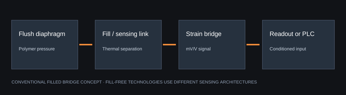
From diaphragm force to a bridge signal
In a conventional filled design, pressure on the tip diaphragm is transmitted to a strain-gauge element through the internal fill. The bridge produces a small differential output. A 3.33 mV/V configuration excited at 10 V produces approximately 33.3 mV at full scale; it needs a compatible bridge input or conditioner.
4–20 mA and 0–10 V require the correct input
A transmitter adds conditioning. For an ideal 0-to-Pmax 4–20 mA configuration, P = (I − 4) / 16 × Pmax, with I in mA. For an ideal 0–10 V configuration, P = V / 10 × Pmax. These scaling relations are not extrusion-flow equations. Polymer pressure drop depends on geometry, throughput, temperature and non-Newtonian rheology.
80% R-Cal checks the electrical chain
First identify the exact model, wiring diagram and permitted calibration procedure. With the machine in its approved safe calibration condition, compare zero and the documented shunt output. For an ideal zero-based 4–20 mA instrument, 80% of span corresponds to 16.8 mA, where this shunt function is supported. A shunt does not apply a known pressure to the diaphragm.
Never pull against solidified polymer
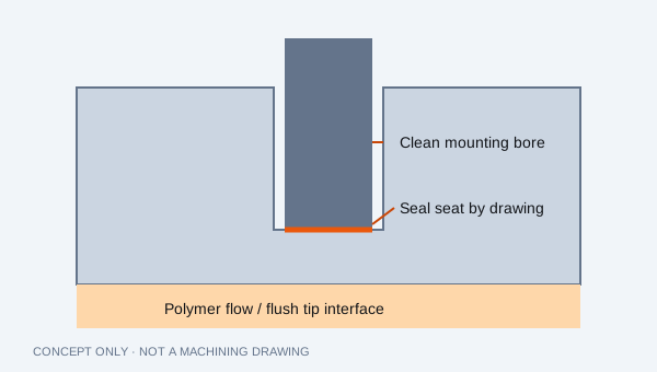
Follow the machine and probe manufacturers’ procedures. Isolate hazardous energy, relieve and verify zero process pressure, and establish the specified heated removal condition so polymer around the tip is softened. Avoid cold forced extraction, scraping the diaphragm and installation into a contaminated or incorrectly machined bore. Use approved PPE and trained maintenance personnel.
Temperature and fill are separate decisions
Confirm melt temperature, electronics ambient, diaphragm material and fill as a complete model specification. Oil-filled and fill-free designs can have different limits. 400°C equals 752°F. Mercury-free selection does not establish food-contact suitability or a harmless leakage scenario.
Primary reference documents
Dynisco Echo operating manual documents bridge / amplified outputs, shunt functions and installation considerations. Dynisco sustainable sensing overview distinguishes fill technologies. These explain industry principles and do not certify an RMP configuration.